实验目的:
1、掌握OSPF的多区域配置。
2、理解OSPF的路由类型<O和O IA路由>。
3、理解OSPF的路由器角色<常规路由器和边界路由器>。
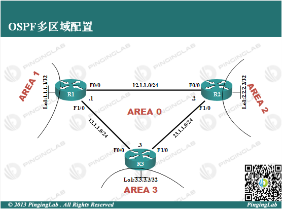
实验拓扑:

实验步骤:
1、依据图中拓扑配置各设备的IP地址,并保证直连连通性;
在R1上做如下配置:
R1(config)#int f0/0

R1(config-if)#no shutdown

R1(config-if)#ip address 12.1.1.1 255.255.255.0

R1(config-if)#exit

R1(config)#int f1/0

R1(config-if)#no shutdown

R1(config-if)#ip address 13.1.1.1 255.255.255.0

R1(config-if)#exit

R1(config)#int loopback 1

R1(config-if)#ip address 1.1.1.1 255.255.255.255

R1(config-if)#exit
在R2上做如下配置:
R2(config)#int f0/0

R2(config-if)#no shutdown

R2(config-if)#ip address 12.1.1.2 255.255.255.0

R2(config-if)#exit

R2(config)#int f1/0

R2(config-if)#no shutdown

R2(config-if)#ip address 23.1.1.2 255.255.255.0

R2(config-if)#exit

R2(config)#int loopback 1

R2(config-if)#ip address 2.2.2.2 255.255.255.255

R2(config-if)#exit
在R3上做如下配置:
R3(config)#int f0/0

R3(config-if)#no shutdown

R3(config-if)#ip address 13.1.1.3 255.255.255.0

R3(config-if)#exit

R3(config-if)#int f1/0

R3(config-if)#no shutdown

R3(config-if)#ip address 23.1.1.3 255.255.255.0

R3(config-if)#exit

R3(config)#int loopback 1

R3(config-if)#ip address 3.3.3.3 255.255.255.255

R3(config-if)#exit
在其中一台路由器上进行连通性测试:
R1#ping 12.1.1.2


Type escape sequence to abort.

Sending 5, 100-byte ICMP Echos to 12.1.1.2, timeout is 2 seconds:

.!!!!

Success rate is 80 percent (4/5), round-trip min/avg/max = 20/34/48 ms

R1#ping 13.1.1.3


Type escape sequence to abort.

Sending 5, 100-byte ICMP Echos to 13.1.1.3, timeout is 2 seconds:

.!!!!

Success rate is 80 percent (4/5), round-trip min/avg/max = 16/31/48 ms
此时说明直连连接没有问题。
2.在每台路由器开始进行OSPF的配置,R1的配置如下:
R1(config)#router ospf 100

R1(config-router)#router-id 1.1.1.1

R1(config-router)#network 12.1.1.0 0.0.0.255 area 0

R1(config-router)#network 13.1.1.0 0.0.0.255 area 0

R1(config-router)#network 1.1.1.1 0.0.0.0 area 1

R1(config-router)#exit
R2的配置如下:
R2(config)#router ospf 100

R2(config-router)#router-id 2.2.2.2

R2(config-router)#network 12.1.1.0 0.0.0.255 area 0

R2(config-router)#network 23.1.1.0 0.0.0.255 area 0

R2(config-router)#network 2.2.2.2 0.0.0.0 area 2

R2(config-router)#exit
R3的配置如下:
R3(config)#router ospf 100

R3(config-router)#router-id 3.3.3.3

R3(config-router)#network 13.1.1.0 0.0.0.255 area 0

R3(config-router)#network 23.1.1.0 0.0.0.255 area 0

R3(config-router)#network 3.3.3.3 0.0.0.0 area 3

R3(config-router)#exit
3、查看OSPF的路由表,在R1上:
R1#show ip route ospf

     2.0.0.0/32 is subnetted, 1 subnets

O IA    2.2.2.2 [110/2] via 12.1.1.2, 00:00:18, FastEthernet0/0

     3.0.0.0/32 is subnetted, 1 subnets

O IA    3.3.3.3 [110/2] via 13.1.1.3, 00:00:18, FastEthernet1/0

     23.0.0.0/24 is subnetted, 1 subnets

O       23.1.1.0 [110/2] via 13.1.1.3, 00:00:18, FastEthernet1/0

                 [110/2] via 12.1.1.2, 00:00:18, FastEthernet0/0
此时可以看到,R1从R2和R3上学到其环回网段,并且路由类型发生变化,从“O”变成”O IA”,前者表示区域内路由,后者表示区域间路由;
由于R1、R2、R3处于区域边界,所以是ABR,可以通过以下命令查看:
R1#show ip protocols

Routing Protocol is "ospf 100"

  Outgoing update filter list for all interfaces is not set

  Incoming update filter list for all interfaces is not set

  Router ID 1.1.1.1

  It is an area border router

  Number of areas in this router is 2. 2 normal 0 stub 0 nssa

  Maximum path: 4

  Routing for Networks:

    1.1.1.1 0.0.0.0 area 1

    12.1.1.0 0.0.0.255 area 0

    13.1.1.0 0.0.0.255 area 0

 Reference bandwidth unit is 100 mbps

  Routing Information Sources:

    Gateway         Distance      Last Update

    3.3.3.3              110      00:06:46

    2.2.2.2              110      00:06:46

  Distance: (default is 110)
4.测试全网连通性,如下:
R1#ping 2.2.2.2 source 1.1.1.1


Type escape sequence to abort.

Sending 5, 100-byte ICMP Echos to 2.2.2.2, timeout is 2 seconds:

Packet sent with a source address of 1.1.1.1

!!!!!

Success rate is 100 percent (5/5), round-trip min/avg/max = 20/27/36 ms

R1#ping 3.3.3.3 so

R1#ping 3.3.3.3 source 1.1.1.1


Type escape sequence to abort.

Sending 5, 100-byte ICMP Echos to 3.3.3.3, timeout is 2 seconds:

Packet sent with a source address of 1.1.1.1

!!!!!

Success rate is 100 percent (5/5), round-trip min/avg/max = 16/22/28 ms
同样的方法在R2和R3上也可以测试连通,说明通过部署OSPF多区域实现全网连通,此实验完成。
- 还没有人评论,欢迎说说您的想法!
